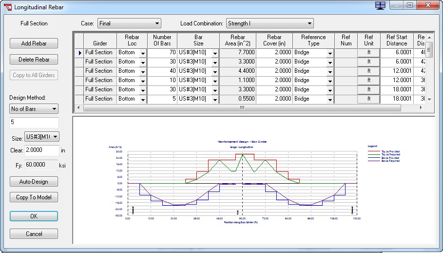
Longitudinal Rebar Definitions Dialog Box
The Longitudinal Rebar Definitions dialog box allows you to define the longitudinal rebar to be used for modeling and/or design. To open this dialog box, click the Long. Rebar button on the Model tab. CIP RC/PT Girder can consider mild reinforcement (i.e. rebar) when determining model stiffness for analysis and will use rebar to determine section capacities.
Adding Rebar Rows
Each girder may contain any number of rebar. In addition, the full section may have any number of rebar. The effect of the rebar defined for the full section will be distributed among the individual girders. Conversely, the effect of the rebar defined for an individual girder will be distributed to the full section. These distributed rebar are automatically generated by LEAP®CIP RC/PT Girder and cannot be edited directly by the user.
- Select the girder section you want to modify from the drop-down list located in the Girder field.
- In the grid, select the rebar row you want to add to by clicking anywhere in its row. A blue arrow displays on the left side of the grid to mark the selection.
- Click the Add Rebar button. This adds a new rebar row after the selected row.
- Enter the rebar row values in the grid. A definition for each parameter is available below.
Copying Rebar Row Values to All Girders
In many cases, several similar rebar exist in all girders. The Copy to All Girders command is used to create a duplicate of the selected rebar in every girder to simplify the definition of similar rebar.
- Select the girder section you want to modify from the drop-down list located in the Girder field.
- In the grid, select the rebar row you want to copy. A blue arrow displays on the left side of the grid to mark the selection.
- Click the Copy to All Girders button to copy the selected row to every girder.
Grid Definitions

| Setting | Description | ||||||||||
|---|---|---|---|---|---|---|---|---|---|---|---|
| Transform Rebar | Click to have rebar transformed for model stiffness. | ||||||||||
| Girder | The girder to which the rebar applies. | ||||||||||
| Rebar Loc | From the drop-down list, select whether the rebar is located on the top or bottom of the girder. This specification is used to identify rebar to be considered for positive and negative moment capacity calculations. "Bottom" rebar will be considered for positive moment capacity and "Top" rebar will be considered for negative moment capacity. | ||||||||||
| Number of Bars | Enter the number of bars needed. | ||||||||||
| Bar Size | Select the bar size from the drop-down list. The bar size name refers to a rebar material definition loaded from the Rebar Library. Rebar material definitions include specification of: unit type, yield stress (fy), ultimate stress (fu), modulus of elasticity, deformed diameter, and area. The Rebar Library can be found under the Libraries menu. Rebar material definitions must be added and deleted from the Rebar Library. An additional rebar size, "unknown," is provided. Use the "unknown" size to enter the rebar area directly. | ||||||||||
| Rebar Area | Displays the total area of rebar for this row if a rebar size is used. Enter the total rebar row area for an "unknown" size. | ||||||||||
| Rebar Cover | Enter the clear cover for this rebar row | ||||||||||
| Reference Type | Select the reference type from the drop-down list.
|
||||||||||
| Ref Num | Reference number when specifying locations by Span or Support. This field will be disabled for the Bridge and Continuous location methods. | ||||||||||
| Ref Unit | Click to define the starting and ending rebar locations as either a percentage or as a distance in the current units. | ||||||||||
| Ref Start Distance | Enter the rebar starting location. | ||||||||||
| Ref End Distance | Enter the rebar ending location. |
Technical Discussion
When the Transform Rebar option is selected,CIP RC/PT Girder will transform all rebar located in the section during model generation.
For reinforced concrete sections CIP RC/PT Girder evaluates serviceability requirements. Evaluating serviceability considers the lateral spacing of the rebar. The lateral spacing of rebar in a rebar row is determined by taking the number of bars and uniformly distributing these bars within the width of the cross-section at the specified depth. Bars specified in the Full Section and falling within the depth of the top or bottom slab are spaced uniformly across the full width of the section. Bars specified in an individual girder are spaced uniformly across the width of the girder section at the depth specified for the rebar.